MODELS 19/19M/20/20M/20P/20MP/200A/200H LIQUID RELIEF VALVES
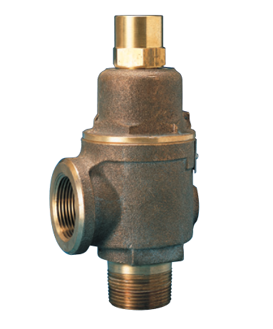
• Inlet and outlet connections cast integral with body for easy inspection and servicing without disconnecting piping.
• Available with optional female NPT inlet or flanged inlet and outlet connections.
• Beveled seats lapped for optimum performance.
• Stainless steel spring for optimum corrosion resistance.
• Spherical pivot between disc and spring corrects misalignment and compensates for spring side thrust.
• Tested and inspected for pressure setting and leakage.
GENERAL APPLICATION
A range of valves suitable for overpressure relief and protection of pumps, tanks, lines and hydraulic systems; pressure regulation and continuous by-pass relief.
TECHNICAL DATA
| Connections: | Threaded NPT or flanged |
| Temperature range: | -60° to 406°F (-51° to 208°C) |
| Pressure range1: | 1 to 500 psig (.07 to 20.7 barg) |
NOTE
1. See specifications table.
MODELS OVERVIEW
Model 19: all bronze, equipped with handwheel for easy adjustment within spring ranges.
Model 19M: as model 19 except SS trim (seat and disc). Available in 2½” and 3″ only. For higher pressure settings or severe applications.
Model 20: all bronze, with pressure-tight cap. Suitable for maximum back pressure of 50 psig (3.45 barg).[1]
Model 20M: as model 20 except SS trim (seat and disc). Available in 2½” and 3″ only. For higher pressure settings or severe applications. Maximum back pressure of 50 psig (3.45 barg).[1]
Model 20P: as model 20 except with packed lift lever. Suitable for maximum back pressure of 50 psig (3.45 barg).[1]
Model 20MP: as model 20M except with packed lift lever. Maximum back pressure of 50 psig (3.45 barg).[1]
Model 200A: special non-chattering design. Recommended for light oils and continuousby-pass or pressure regulation. UL842 listed for light oil service. Available in ¾” to 1½” sizes. Female NPT connections only.
Model 200H: as model 20. UL842 listed for use with fuel oils. Available in ¾” to 2″ sizes.
OPTIONS
• Available with optional female NPT inlet or flanged inlet and outlet connections.
• Model 19
Variation 10: 5 to 75 psig (.34 to 5.17 barg) adjustable spring range.
Variation 11: 75 to 150 psig (5.17 to 10.34 barg) adjustable spring range.
Variation 12: 150 to 300 psig (10.34 to 20.7 barg) adjustable spring range.
•Models 19-D and 20-D
Variation 05: 50 to 150 psig (3.45 to 10.34 barg) spring range.
Variation 06: 100 to 300 psig (6.9 to 20.7 barg)spring range.
NOTE
1. Back pressure increases set pressure on a one to one basis and reduces capacity. Back pressure in excess of 10% of set pressure is not recommended.
PARTS AND MATERIALS
| No. | Part Name | 19, 19M | 20, 20M, 20P, 20MP, 200A, 200H |
| 1 | Body1 | Bronze B62 | Bronze B62 |
| 2 | Stem retainer | Brass B16 | Brass B16 |
| 3 | Disc | Bronze B584 Alloy 84400[2,3] | Bronze B584 Alloy 84400[2,3] |
| 4 | Spring step | Brass B16 | Brass B16 |
| 5 | O-ring | PTFE | PTFE |
| 6 | Spring | SS 316 or 17-7 | SS 316 or 17-7 |
| 7 | Stem | Brass B16 | Brass B16 |
| 8 | Bonnet | Bronze B584 Alloy 84400 | Bronze B584 Alloy 84400 |
| 9 | Jam nut | Steel A108 zinc plated | Brass B16 |
| 10 | Compression screw | Brass B16 | Brass B16 |
| 11 | Cap | N/A | Brass, B16 |
| 12 | O-ring | N/A | NBR |
| 13 | Drive screw6 | SS commercial | SS commercial |
| 14 | Handwheel | Iron A126 zinc plated5 | N/A |
NOTES
1. Flanged connections optional.
2. Models 19, 20, 20P, 200H are brass, B283, Alloy 485, for ½”, ¾”, and 1”.
3. Models 19M, 20M, and 20MP are SS A743-CF8.
4. Model 200A is brass B16.
5. Bronze B584 Alloy 84400 for ½”, ¾”, 1¼”.
6. Not used on bonnet for 2½” and 3”.
MODELS 20, 200H WITH PRESSURE TIGHT CAP
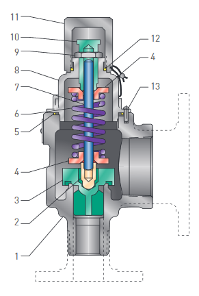
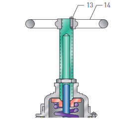
MODEL 19, 19M
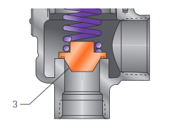
MODEL 200A
PARTS AND MATERIALS
| No. | Part Name | Material |
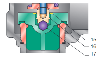
| 15 | Retainer washer | SS PH15-7MO |
| 16 | Stem end | SS A582-303 |
| 17 | Ball | SS A756-440 |
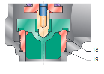
| 18 | Insert | SS A743 GR CF8 |
| 19 | O-ring | PTFE |
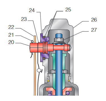
| 20 | Lift cam | SS A743-316 |
| 21 | Cotter pin | Steel |
| 22 | Lever | Steel A108 zinc plated |
| 23 | Drive screw | SS Commercial |
| 24 | Retainer cam | Brass B16 |
| 25 | O-ring | NBR |
| 26 | Cap | Bronze B584 Alloy 84400 |
| 27 | Lift nut | Steel A108 |
MODELS 19M, 20M AND 20MP 2½” SEAT CONFIGURATION
MODELS 19M, 20M AND 20MP 3” SEAT CONFIGURATION
MODELS 20MP AND 20P WITH LEVER
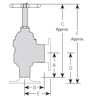
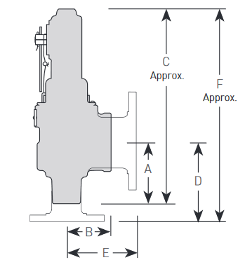
DIMENSIONS (inches)
| Threaded | 150/300 flange | |||||
| Valve model | A | B | C | D | E | F |
| 1¼” Size | ||||||
| 19 | 2⅝ | 21/16 | 8⅛ | 311/16 | 311/16 | 9⅛ |
| 20 | 2⅝ | 21/16 | 8⅛ | 311/16 | 311/16 | 8⅜ |
| 20P | 2⅝ | 21/16 | 9 | 311/16 | 311/16 | 10 |
| 200A | 2⅝ | 21/16 | 7⅜ | - | - | - |
| 200H | 2⅝ | 21/16 | 7⅜ | 311/16 | 311/16 | 8⅝ |
| 1½” Size | ||||||
| 19 | 211/16 | 2⅛ | 8⅝ | 4⅛ | 4⅛ | 10⅛ |
| 20 | 211/16 | 2⅛ | 8⅝ | 4⅛ | 4⅛ | 9¼ |
| 20P | 211/16 | 2⅛ | 9¼ | 4⅛ | 4⅛ | 10¾ |
| 200A | 211/16 | 2⅛ | 7⅞ | - | - | - |
| 200H | 211/16 | 2⅛ | 7⅞ | 4⅛ | 4⅛ | 9½ |
| 2” Size | ||||||
| 19 | 3½ | 211/16 | 10⅝ | 4¼ | 4¼ | 11¼ |
| 20 | 3½ | 211/16 | 10⅝ | 4¼ | 4¼ | 10⅝ |
| 20P | 3½ | 211/16 | 12½ | 4¼ | 4¼ | 13⅛ |
| 200H | 3½ | 211/16 | 915/16 | 4½ | 4¼ | 1015/16 |
| 2½” Size | ||||||
| 19 | 3⅞ | 200H | 11⅛ | 4¾ | 4¾ | 12 |
| 19M | 3⅞ | 3 | 11⅛ | 4¾ | 4¾ | 12¼ |
| 20 | 3⅞ | 3 | 10 | 4¾ | 4¾ | 1315/16 |
| 20M | 3⅞ | 3 | 10 | 4¾ | 4¾ | 139/16 |
| 20P | 3⅞ | 3 | 12½ | 4¾ | 4¾ | 15¾ |
| 20MP | 3⅞ | 3 | 12½ | 54¾ | 4¾ | 161/16 |
| 3” Size | ||||||
| 19 | 4⅝ | 3⅞ | 12¼ | 5 | 5 | 12⅝ |
| 19M | 4⅝ | 3⅞ | 12¼ | 5 | 5 | 13⅛ |
| 20 | 4⅝ | 3⅞ | 12¼ | 5 | 5 | 14¾ |
| 20M | 4⅝ | 3⅞ | 12¼ | 5 | 5 | 15⅛ |
| 20P | 4⅝ | 3⅞ | 14⅜ | 5 | 5 | 16⅞ |
| 20MP | 4⅝ | 3⅞ | 14⅜ | 5 | 5 | 17¼ |
Dimensions are for reference only
NOTES
1. All flanges rated per ANSI B16.24.
2. Standard with ¾” outlet – ½” outlet optional.
MODELS 19, 19M
MODELS 20, 20M, 200A, 200H
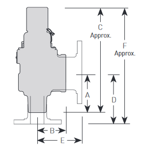
MODELS 20P, 20MP
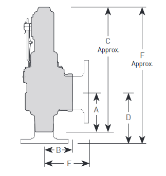
SPECIFICATIONS
| Size | Min/max | Min/max | Approximate | ||
| inlet/outlet | set pressure, (psig)[1] | temperature | weight | ||
| NPT, (in) | 19, 20, 20P | 200A, 200H | 19M, 20M, 20MP | (°F) | (lb) |
| ½[2] | 1/300 | — | — | -60/406 | 2¼ |
| ¾ | 1/300 | 1/200 | — | -60/406 | 2¼ |
| 1 | 1/300 | 1/200 | — | -60/406 | 3½ |
| 1¼ | 1/300 | 1/200 | — | -60/406 | 5 |
| 1½ | 1/300 | 1/200 | — | -60/406 | 6¼ |
| 2 | 1/300 | 1/200 | — | -60/406 | 11 |
| 2½ | 1/300 | — | 1/500 | -60/406 | 16 |
| 3 | 1/300 | — | 1/500 | -60/406 | 25 |
DIMENSIONS (inches)
| Threaded | 150/300 flange | |||||
| Valve model | A | B | C | D | E | F |
| ½” Size | ||||||
| 19 | 2 | 1⅝ | 6⅛ | 35/16 | 35/16 | 7⅜ |
| 20 | 2 | 1⅝ | 5⅞ | 35/16 | 35/16 | 7¼ |
| 20P | 2 | 1⅝ | 7⅜ | - | - | - |
| ¾” Size | ||||||
| 19 | 2 | 1⅝ | 6⅛ | 35/16 | 35/16 | 7⅜ |
| 20 | 2 | 1⅝ | 5⅞ | 35/16 | 35/16 | 7¼ |
| 20P | 2 | 1⅝ | 7⅜ | 35/16 | 35/16 | 8¾ |
| 200A | 2 | 1⅝ | 5⅞ | - | - | - |
| 200H | 115/16 | 1⅝ | 5⅞ | 35/16 | 35/16 | 7⅜ |
| 1” Size | ||||||
| 19 | 2¼ | 1⅞ | 7⅛ | 37/16 | 37/16 | 8¼ |
| 20 | 2¼ | 1⅞ | 6¾ | 37/16 | 37/16 | 7⅞ |
| 20P | 2¼ | 1⅞ | 8¾ | 37/16 | 37/16 | 9½ |
| 200A | 2¼ | 1⅞ | 6¾ | - | - | - |
| 200H | 2¼ | 1⅞ | 611/16 | 37/16 | 37/16 | 8 |
Dimensions are for reference only
MODELS 19, 19M
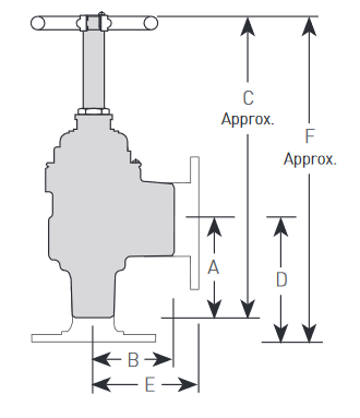
MODELS 20, 20M, 200A, 200H
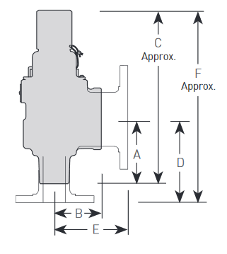
MODELS 20P, 20MP
NON-CODE LIQUID CAPACITY – 25% ACCUMULATION (GPM)
| Set pressure | Valve | inlet | and | outlet | size | |||
| (psig) | ½” | ¾” | 1” | 1¼” | 1½” | 2” | 2½” | 3” |
| 1 | 1 | 2 | 4 | 6 | 10 | 19 | 31 | 45 |
| 5 | 2 | 5 | 8 | 14 | 22 | 42 | 68 | 100 |
| 10 | 3 | 7 | 11 | 20 | 31 | 59 | 97 | 141 |
| 20 | 4 | 9 | 16 | 28 | 43 | 84 | 137 | 200 |
| 30 | 5 | 11 | 20 | 34 | 53 | 102 | 168 | 244 |
| 40 | 6 | 13 | 23 | 39 | 61 | 118 | 193 | 282 |
| 50 | 7 | 15 | 25 | 44 | 68 | 132 | 216 | 315 |
| 60 | 7 | 16 | 28 | 48 | 75 | 145 | 237 | 346 |
| 70 | 8 | 17 | 30 | 52 | 81 | 156 | 256 | 373 |
| 80 | 8 | 19 | 32 | 55 | 87 | 167 | 274 | 399 |
| 90 | 9 | 20 | 34 | 59 | 92 | 177 | 290 | 423 |
| 100 | 9 | 21 | 36 | 62 | 97 | 187 | 306 | 446 |
| 110 | 10 | 22 | 37 | 65 | 102 | 196 | 321 | 468 |
| 120 | 10 | 23 | 39 | 68 | 106 | 205 | 335 | 489 |
| 130 | 11 | 24 | 41 | 71 | 110 | 213 | 349 | 509 |
| 140 | 11 | 25 | 42 | 73 | 115 | 221 | 362 | 528 |
| 150 | 11 | 25 | 44 | 76 | 119 | 229 | 375 | 546 |
| 160 | 12 | 26 | 45 | 78 | 123 | 236 | 387 | 564 |
| 170 | 12 | 27 | 47 | 81 | 126 | 244 | 399 | 582 |
| 180 | 13 | 28 | 48 | 83 | 130 | 251 | 410 | 599 |
| 190 | 13 | 29 | 49 | 86 | 134 | 258 | 422 | 615 |
| 200 | 13 | 29 | 50 | 88 | 137 | 264 | 433 | 631 |
| 210 | 14 | 30 | 52 | 90 | 140 | 271 | 443 | 646 |
| 220 | 14 | 31 | 53 | 92 | 144 | 277 | 454 | 662 |
| 230 | 14 | 32 | 54 | 94 | 147 | 284 | 464 | 677 |
| 240 | 14 | 32 | 55 | 96 | 150 | 290 | 474 | 691 |
NOTE
1. Liquid overpressure factors
To determine capacities at other than 25% overpressure/accumulation, multiply capacity shown by:
10% acc. = 0.6
15% acc. = 0.8
20% acc. = 0.9
NON-CODE LIQUID CAPACITY – 25% ACCUMULATION (GPM)
| Set pressure | Valve | inlet | and | outlet | size | |||
| (psig) | ½” | ¾” | 1” | 1¼” | 1½” | 2” | 2½” | 3” |
| 250 | 15 | 33 | 56 | 98 | 153 | 484 | 705 | |
| 260 | 15 | 34 | 58 | 100 | 156 | 301 | 493 | 719 |
| 270 | 15 | 34 | 59 | 102 | 159 | 307 | 503 | 733 |
| 280 | 16 | 35 | 60 | 104 | 162 | 313 | 512 | 746 |
| 290 | 16 | 35 | 61 | 106 | 165 | 318 | 521 | 760 |
| 300 | 16 | 36 | 62 | 107 | 168 | 323 | 530 | 773 |
| 310 | - | - | - | - | - | - | 539 | 785 |
| 320 | - | - | - | - | - | - | 547 | 798 |
| 330 | - | - | - | - | - | - | 556 | 810 |
| 340 | - | - | - | - | - | - | 564 | 823 |
| 350 | - | - | - | - | - | - | 572 | 835 |
| 360 | - | - | - | - | - | - | 580 | 846 |
| 370 | - | - | - | - | - | - | 588 | 858 |
| 380 | - | - | - | - | - | - | 596 | 870 |
| 390 | - | - | - | - | - | - | 604 | 881 |
| 400 | - | - | - | - | - | - | 612 | 892 |
| 410 | - | - | - | - | - | - | 619 | 903 |
| 420 | - | - | - | - | - | - | 627 | 914 |
| 430 | - | - | - | - | - | - | 634 | 925 |
| 440 | - | - | - | - | - | - | 642 | 936 |
| 450 | - | - | - | - | - | - | 649 | 946 |
| 460 | - | - | - | - | - | - | 656 | 957 |
| 470 | - | - | - | - | - | - | 663 | 967 |
| 480 | - | - | - | - | - | - | 670 | 977 |
| 490 | - | - | - | - | - | - | 677 | 987 |
| 500 | - | - | - | - | - | - | 684 | 998 |
NOTE
1. Liquid overpressure factors
To determine capacities at other than 25% overpressure/accumulation, multiply capacity shown by:
10% acc. = 0.6
15% acc. = 0.8
20% acc. = 0.9
MODEL 200A ‘D’ – ¾”
| Overpressure | ||||
| psi | 25% | 50% | 75% | 100% |
| 5 | 1.2 | 1.9 | 2.7 | 3.7 |
| 10 | 1.2 | 2.0 | 2.8 | 4.4 |
| 15 | 1.3 | 2.0 | 2.9 | 4.7 |
| 20 | 1.5 | 2.2 | 3.0 | 5.2 |
| 25 | 1.5 | 2.2 | 3.0 | 6.0 |
| 30 | 1.5 | 2.2 | 3.1 | 6.5 |
| 35 | 1.5 | 2.5 | 3.3 | 7.4 |
| 40 | 1.7 | 2.6 | 3.5 | 8.5 |
| 45 | 1.9 | 2.8 | 3.6 | 9.6 |
| 50 | 2.0 | 3.0 | 3.8 | 11.0 |
| 55 | 2.2 | 3.2 | 4.0 | 12.2 |
| 60 | 2.3 | 3.4 | 4.2 | 13.5 |
| 65 | 2.4 | 3.5 | 4.4 | 14.8 |
| 70 | 2.5 | 3.7 | 4.5 | 16.0 |
| 75 | 2.6 | 4.0 | 4.7 | 17.1 |
| 80 | 2.8 | 4.2 | 5.0 | 18.2 |
| 85 | 2.9 | 4.4 | 5.1 | 19.3 |
| 90 | 3.0 | 4.6 | 5.4 | 20.2 |
| 95 | 3.1 | 4.7 | 5.5 | 21.0 |
| 100 | 3.1 | 4.8 | 5.7 | 21.4 |
| 105 | 3.3 | 5.0 | 6.0 | 21.5 |
| 110 | 3.4 | 5.1 | 6.1 | 21.4 |
| 115 | 3.4 | 5.3 | 6.2 | 21.0 |
| 120 | 3.5 | 5.5 | 6.4 | 20.5 |
| 125 | 3.5 | 5.6 | 6.5 | 20.2 |
| 130 | 3.5 | 5.8 | 6.7 | 19.8 |
| 135 | 3.7 | 6.0 | 6.9 | 20.0 |
| 140 | 3.7 | 6.1 | 7.0 | 20.2 |
| 145 | 3.8 | 6.2 | 7.0 | 20.8 |
| 150 | 3.8 | 6.3 | 7.2 | 21.5 |
| 155 | 4.0 | 6.5 | 7.4 | 22.0 |
| 160 | 4.0 | 6.5 | 7.5 | 22.9 |
| 165 | 4.0 | 6.5 | 7.6 | 23.7 |
| 170 | 4.0 | 6.6 | 7.8 | 24.6 |
| 175 | 4.1 | 6.8 | 8.2 | 25.5 |
| 180 | 4.2 | 6.9 | 8.5 | 26.8 |
| 185 | 4.3 | 6.9 | 9.0 | 28.5 |
| 190 | 4.4 | 7.0 | 10.0 | 30.5 |
| 195 | 4.4 | 7.0 | 11.5 | 33.5 |
| 200 | 4.5 | 7.0 | 12.9 | 36.2 |
MODEL 200A ‘E’ – 1”
| Overpressure | ||||
| psi | 25% | 50% | 75% | 100% |
| 5 | 0.7 | 1.0 | 1.3 | 2.5 |
| 10 | 1.1 | 1.5 | 2.0 | 4.2 |
| 15 | 1.5 | 2.0 | 2.7 | 5.9 |
| 20 | 1.7 | 2.5 | 3.5 | 7.5 |
| 25 | 2.0 | 2.9 | 4.1 | 9.5 |
| 30 | 2.2 | 3.2 | 4.6 | 11.0 |
| 35 | 2.5 | 3.6 | 5.0 | 12.9 |
| 40 | 2.6 | 4.0 | 5.5 | 14.5 |
| 45 | 2.8 | 4.2 | 5.8 | 16.5 |
| 50 | 2.9 | 4.5 | 6.0 | 18.4 |
| 55 | 3.0 | 4.8 | 6.4 | 20.1 |
| 60 | 3.2 | 5.0 | 6.6 | 22.0 |
| 65 | 3.4 | 5.2 | 6.8 | 24.0 |
| 70 | 3.5 | 5.5 | 7.1 | 26.0 |
| 75 | 3.5 | 5.7 | 7.3 | 27.8 |
| 80 | 3.6 | 6.1 | 7.5 | 29.5 |
| 85 | 3.8 | 6.4 | 7.7 | 31.0 |
| 90 | 3.9 | 6.7 | 8.1 | 32.7 |
| 95 | 4.0 | 6.9 | 8.2 | 34.2 |
| 100 | 4.1 | 7.0 | 8.5 | 35.5 |
| 105 | 4.3 | 7.2 | 8.7 | 37.0 |
| 110 | 4.4 | 7.4 | 9.0 | 38.0 |
| 115 | 4.5 | 7.5 | 9.1 | 39.0 |
| 120 | 4.5 | 7.6 | 9.2 | 39.8 |
| 125 | 4.7 | 7.7 | 9.5 | 40.2 |
| 130 | 4.8 | 7.8 | 9.6 | 40.5 |
| 135 | 4.8 | 8.0 | 9.7 | 40.5 |
| 140 | 4.9 | 8.0 | 9.8 | 40.1 |
| 145 | 5.0 | 8.4 | 10.0 | 39.5 |
| 150 | 5.0 | 8.5 | 10.0 | 38.3 |
| 155 | 5.0 | 8.5 | 10.2 | 37.2 |
| 160 | 5.1 | 8.7 | 10.4 | 36.0 |
| 165 | 5.2 | 9.0 | 10.5 | 34.8 |
| 170 | 5.4 | 9.2 | 10.8 | 33.7 |
| 175 | 5.5 | 9.4 | 10.9 | 33.0 |
| 180 | 5.5 | 9.5 | 11.0 | 33.0 |
| 185 | 5.5 | 9.5 | 11.2 | 34.2 |
| 190 | 5.4 | 9.5 | 11.3 | 37.5 |
| 195 | 5.2 | 9.5 | 11.5 | 43.5 |
| 200 | 5.0 | 9.5 | 11.6 | 48.8 |
MODEL 200A ‘F’ – 1¼”
| Overpressure | ||||
| psi | 25% | 50% | 75% | 100% |
| 5 | 1.0 | 4.0 | 5.0 | 7.0 |
| 10 | 2.5 | 7.0 | 7.0 | 13.5 |
| 15 | 4.0 | 10.0 | 12.5 | 20.0 |
| 20 | 5.0 | 14.0 | 16.5 | 27.5 |
| 25 | 7.5 | 18.0 | 21.5 | 35.0 |
| 30 | 8.0 | 20.2 | 25.0 | 41.5 |
| 35 | 9.5 | 25.5 | 29.5 | 48.5 |
| 40 | 10.0 | 27.0 | 33.5 | 54.5 |
| 45 | 11.0 | 28.2 | 38.0 | 60.0 |
| 50 | 11.8 | 30.0 | 42.5 | 66.5 |
| 55 | 12.5 | 31.5 | 47.5 | 73.0 |
| 60 | 13.0 | 33.0 | 52.0 | 79.0 |
| 65 | 14.0 | 34.5 | 56.5 | 85.5 |
| 70 | 14.8 | 36.0 | 61.0 | 92.0 |
| 75 | 15.5 | 37.7 | 65.5 | 97.5 |
| 80 | 16.2 | 39.0 | 69.5 | 102.7 |
| 85 | 17.0 | 40.0 | 73.0 | 108.0 |
| 90 | 18.0 | 41.0 | 76.0 | 112.0 |
| 95 | 18.5 | 42.0 | 78.0 | 115.5 |
| 100 | 17.5 | 42.0 | 78.5 | 116.7 |
| 105 | 16.5 | 41.0 | 77.5 | 115.7 |
| 110 | 15.5 | 39.5 | 74.5 | 113.0 |
| 115 | 14.5 | 37.5 | 70.5 | 108.5 |
| 120 | 13.5 | 35.0 | 66.0 | 103.5 |
| 125 | 12.5 | 33.7 | 62.7 | 99.8 |
| 130 | 11.5 | 33.0 | 60.0 | 98.0 |
| 135 | 10.5 | 33.5 | 60.5 | 99.0 |
| 140 | 11.8 | 35.0 | 63.0 | 103.0 |
| 145 | 13.0 | 37.5 | 66.5 | 109.0 |
| 150 | 14.5 | 40.0 | 71.0 | 116.0 |
| 155 | 16.0 | 43.5 | 76.0 | 123.7 |
| 160 | 17.2 | 47.0 | 81.5 | 132.0 |
| 165 | 18.8 | 50.5 | 87.0 | 140.0 |
| 170 | 20.0 | 54.0 | 92.5 | 148.0 |
| 175 | 21.5 | 57.8 | 97.5 | 155.5 |
| 180 | 23.0 | 61.0 | 102.0 | 160.5 |
| 185 | 24.0 | 63.5 | 105.0 | 163.0 |
| 190 | 25.0 | 65.5 | 106.0 | 160.0 |
| 195 | 26.2 | 67.5 | 106.5 | 153.5 |
| 200 | 27.5 | 69.0 | 106.8 | 147.5 |
MODEL 200A ‘G’ – 1½”
| Overpressure | ||||
| psi | 25% | 50% | 75% | 100% |
| 5 | 1.5 | 2.2 | 4.5 | 8.5 |
| 10 | 2.0 | 3.2 | 8.7 | 18.0 |
| 15 | 2.8 | 4.3 | 13.0 | 27.9 |
| 20 | 3.4 | 5.3 | 17.0 | 37.0 |
| 25 | 3.8 | 6.2 | 20.8 | 44.5 |
| 30 | 4.0 | 6.8 | 24.0 | 51.8 |
| 35 | 4.5 | 7.5 | 27.0 | 57.7 |
| 40 | 5.0 | 8.0 | 30.0 | 62.5 |
| 45 | 5.0 | 8.3 | 32.5 | 67.5 |
| 50 | 5.5 | 8.5 | 35.0 | 72.0 |
| 55 | 5.7 | 8.9 | 37.7 | 76.5 |
| 60 | 6.0 | 9.5 | 40.0 | 80.5 |
| 65 | 6.5 | 9.5 | 42.5 | 84.5 |
| 70 | 6.5 | 9.7 | 45.0 | 88.3 |
| 75 | 6.7 | 9.8 | 47.0 | 91.7 |
| 80 | 6.7 | 10.0 | 49.0 | 94.7 |
| 85 | 6.8 | 10.0 | 51.0 | 97.5 |
| 90 | 7.0 | 10.3 | 53.0 | 99.5 |
| 95 | 7.2 | 10.5 | 54.0 | 100.6 |
| 100 | 7.2 | 11.0 | 55.0 | 100.3 |
| 105 | 7.5 | 11.0 | 54.0 | 97.5 |
| 110 | 7.5 | 11.3 | 53.0 | 93.0 |
| 115 | 7.5 | 11.7 | 51.0 | 87.0 |
| 120 | 7.5 | 11.8 | 49.0 | 80.5 |
| 125 | 7.7 | 12.0 | 47.5 | 75.5 |
| 130 | 7.9 | 12.0 | 46.8 | 73.0 |
| 135 | 8.0 | 12.2 | 47.2 | 73.5 |
| 140 | 8.0 | 12.2 | 48.7 | 77.0 |
| 145 | 8.0 | 12.4 | 50.7 | 83.0 |
| 150 | 8.0 | 12.4 | 53.0 | 90.0 |
| 155 | 8.0 | 12.4 | 56.0 | 98.0 |
| 160 | 8.0 | 12.4 | 59.0 | 106.5 |
| 165 | 8.0 | 12.5 | 62.3 | 115.7 |
| 170 | 8.0 | 12.7 | 65.5 | 124.5 |
| 175 | 8.0 | 13.0 | 69.0 | 133.5 |
| 180 | 8.5 | 14.0 | 73.0 | 140.5 |
| 185 | 9.0 | 15.8 | 77.0 | 146.0 |
| 190 | 10.0 | 19.0 | 82.5 | 150.0 |
| 195 | 11.8 | 23.5 | 89.0 | 152.2 |
| 200 | 13.5 | 27.7 | 95.5 | 154.7 |
SELECTION GUIDE
| Example: | 0019 | - | F | 01 | - | G | 0075 |
| Model 0019 019M 0020 020M 020P 20MP 200A 200H | |||||||
| Inlet size C ½” G 1½” D ¾” H 2” E 1” J 2½” F 1¼” K 3” | |||||||
| Variation See chart page | |||||||
| Design revision Indicates non-interchangeable revision. Dash (-) if original design. | |||||||
| Spring material G 316 SS H 304 SS (only for Model 19M-K 300 psig or greater) | |||||||
| Set pressure 0005 5 psig 0025 25 psig 0400 400psig |
| Variation | ||||||||||||||||||
| ½” Male x ¾” female | ½” Male x ½” female | ½” Female x ¾” female | Male x female with gag | ½” Female x ½” female | ½” 150 Flg x ½” 150 Flg | ½” 300 Flg x ½” 150 Flg | Male x female | Female x female (200A) | Female x female | 150 Flg x 150 Flg | 300 Flg x 150 Flg (200H) | 300 Flg x 150 Flg | 150 Flg x 150 Flg (200H) | ¾” 300 Flg x ¾” 150 Flg (020P-D) | Male x female (19-D, 20-D) 50 to 150 psig | Male x female (19-D, 20-D) 100 to 300 psig | ||
| Model - inlet size | Inlet x outlet | 01 | 02 | 03 | 03 | 04 | 05 | 061 | 01 | 01 | 02 | 03 | 03 | 04 | 04 | 05 | 05 | 06 |
| 19-C, 20-C, 20P-C | ½” x ½” (¾”) | X | X | X | X | X | X | |||||||||||
| 19-D, 20-D | ¾” x ¾” | X | X | X | X | X | X | |||||||||||
| 200A-D | ¾” x ¾” | X | X | |||||||||||||||
| 200H-D | ¾” x ¾” | X | X | X | ||||||||||||||
| 19-E, 20-E, 20P-E2 | 1” x 1” | X | X | X | X | |||||||||||||
| 200A-E | 1” x 1” | X | X | X | ||||||||||||||
| 200H-E | 1” x 1” | X | X | X | ||||||||||||||
| 19-F, 20-F, 20P-F2 | 1¼” x 1¼” | X | X | X | X | |||||||||||||
| 200A-F | 1¼” x 1¼” | X | X | |||||||||||||||
| 200H-F | 1¼” x 1¼” | X | X | X | ||||||||||||||
| 19-G, 20-G, 20P-G2 | 1½” x 1½” | X | X | X | X | |||||||||||||
| 200A-G | 1½” x 1½” | X | X | |||||||||||||||
| 200H-G | 1½” x 1½” | X | X | X | ||||||||||||||
| 19-H, 20-H, 20P-H2 | 2” x 2” | X | X | X | X | X | ||||||||||||
| 200H-H | 2” x 2” | X | X | X | ||||||||||||||
| 19-J, 19M-J, 20J, 20P-J, 20M-J, 20MP-J | 2½” x 2½” | X | X | X | X | |||||||||||||
| 19-K, 19M-K, 20-K, 20P-K, 20M-K, 20MP-K | 3” x 3” | X | X | X | X | |||||||||||||
| 20P-D | ¾” x ¾” | X | X | X | X | X |
